Preamble
Due to the problems of difficult chip removal, high straightness requirements and difficult tool design in the deep hole machining of aero-engine casings, the machining efficiency is generally low [1]. The deep hole of a certain type of aero-engine accessory transmission casing has always been processed by drilling and boring, which requires frequent tool retraction to remove chips, accounting for 80% of the processing time. It is also necessary to reduce the rotational speed and feed speed while idling the tool to avoid cutting tools. Scratching the exit of the hole, this processing method is not only inefficient, but also difficult to guarantee the position and straightness of the hole, and there is a quality risk of scrapped parts. If the parts are scrapped, each piece will lose more than 100,000 yuan, resulting in greater economic losses and greater work pressure for operators. It is urgent to improve and innovate this processing technology, otherwise it will be difficult to adapt to the rapid development of enterprises. This paper overcomes the key technology of intermittent deep hole NC machining by means of process integration optimization, tool improvement and machining technical scheme optimization, which greatly improves machining efficiency while ensuring machining quality.
Process difficulty analysis
2.1 Processing requirements of typical parts
Figure 1 shows the technical requirements for machining intermittent deep holes in the accessory drive casing. The depth of the hole is 790.5mm, and the aspect ratio reaches 44:1. The hole is divided into two sections by the hollow part with a length of 181.7mm in the middle. The diameter of the first half of the hole is 19mm, and the diameter of the second half of the hole is 18mm. mm, the two sections of holes are concentric holes, and the surface roughness value Ra of the holes is required to be 1.6 μm.
Figure 1 Technical requirements for intermittent deep hole in a casing
2.2 Processing difficulties of typical parts
The processing difficulties are as follows.
1) The two holes to be machined are deep holes with a large aspect ratio. The tools required for processing are very slender, with poor rigidity, difficulty in chip removal, and low processing efficiency.
2) Intermittent deep hole processing is shown in Figure 2. It is difficult to center the drill bit at the hollow discontinuity, and it is easy to drill off. The hole needs to pass through two rib plates. After processing, the wall thickness of the rib plate is only 2.0-2.5mm. If the drilling position is not well controlled, it will drill through the support plate, resulting in scrapped parts. It is one of the typical types of deep holes that are difficult to machine.
Deep hole machining technology
3.1 Original processing technology scheme
The original process method of deep hole processing (see Figure 3) is: φ 24mm buried drill (end face of buried flat hole) → φ10mm center drill (drill center hole) → φ 16mm drill bit roughing the first half of the hole → φ 19mm boring tool boring at the hole Do guide → φ 19mm flat bottom submerged drilling (processing the φ19mm diameter part, and bury the end face of the φ18mm hole at the discontinuity) → φ 18mm long drill bit to process the deep hole at a slow speed → φ18mm submerged drilling and finishing the φ18mm hole.
3.2 Problems with processing methods
- There are many tools, many working steps, and low cutting parameters of the tools. The hole processing time is up to 150min, the efficiency is very low, intermittent deep hole tool processing
- The hole over-tolerance loss is large. The twist drill has poor centering, difficult chip removal, low drilling accuracy, easy drilling deviation, unstable quality, and a loss of nearly 300,000 yuan a year.
A New Plan for Intermittent Deep Hole Machining of Aluminum Magnesium Gate
4.1 New solutions for processing
The design of a new deep hole machining scheme is shown in Figure 4.
(1) Change the processing method of the pilot hole. Change the 4 working steps of buried end face, machining center hole, rough drilling and boring to 1-step processing of three-blade drilling. Using the characteristics of good centering of the three-blade drill and the hole position accuracy can reach 0.03 ~ 0.1mm, the processing effect of the four knives in the original process method can be achieved, and the efficiency is increased by 7 times compared with the original process method.
(2) Improve the drill for deep hole processing Use a φ18mm gun drill instead of a φ18mm long twist drill. The gun drill has strong advantages, its rigidity is good, the speed can reach 3000r/min, the tool has internal cooling, easy chip removal, no repeated cycle retraction during processing, and high cutting line speed, which can increase the processing speed by more than 10 times. , but also can improve the hole position accuracy and surface quality.
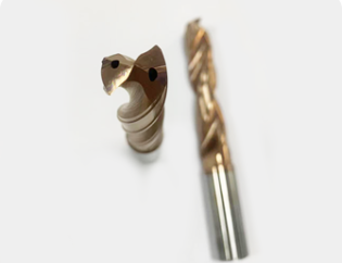
(3) Reduction of machining tools The original 7 tools are reduced to 3 tools. Two φ18mm three-blade pilot drills with a length of 200mm and 410mm are used to process the pilot holes, and a φ18mm gun drill is used to process the intermittent holes. The comparison of the tool scheme before and after the improvement is shown in Figure 5.
(4) Replacement of processing equipment The original processing equipment is a horizontal four-axis machining center with no internal cooling and no external cooling, which restricts the selection of cutting parameters due to poor cooling and chip removal effects. After the improvement, a five-axis gantry machining center with high-pressure center internal cooling was selected, which has good cooling, lubricating and chip removal effects, laying a foundation for high-speed machining.
a) Original tool plan b) New tool plan
Figure 5 Comparison of tool schemes before and after improvement
4.2 Matching requirements of gun drill and pilot drill and processing depth of pilot hole
For deep hole machining with a large aspect ratio, a guide drill with suitable accuracy is required when using a gun drill [2]. For the φ18mm gun drill used, its own accuracy should be controlled within ±0.01mm, and the guide hole diameter tolerance should also be controlled within ±0.008mm. In addition to the manufacturing accuracy, the gap value between the gun drill and the pilot drill is also very important, because if the gap is too large, the pilot hole will lose the role of accurate guidance. According to the processing test, the matching clearance between the guide hole and the gun drill should be controlled within 0.01-0.02mm. Pilot drills generally have short cutting edges and good rigidity, but the drilling depth is shallow. In order to make the guide hole ensure that the gun drill is not biased and have the best guiding effect, the processing test is carried out with reference to the length of the drill sleeve used when processing deep holes by ordinary drilling machines. The test results show that the depth of the guide hole should be 2.5 of the diameter of the gun drill. ~ 3 times, such as processing a φ18mm deep hole, the depth of the guide hole is 54mm.
4.3 Programming
Only relying on the above processing scheme cannot realize the processing of holes, and the scheme needs to be converted into a language recognized by the machine, that is, NC programming. The programming needs to be comprehensively considered, such as the installation of the tool, the machining sequence of the tool, the tool path, cutting parameters and whether it interferes [3]. operate.
(1) Main points of the gun drill processing program The gun drill processing command selects CYCLE83[4], but before executing CYCLE83, the gun drill should also enter the pilot hole smoothly and accurately. First use S50 low speed, F200 slow feed to execute G01 command, enter the already machined guide hole with a depth of 48mm, then start the internal cooling, and prepare to execute CYCLE83. The speed in CYCLE83 is increased to S600, the feed rate is F90, and the first drilling depth of CYCLE83 command is set to 1 times the diameter, that is, 18mm, and the first feed rate is set to 50%, that is, F45; during machining, use chip breaking method, the retraction distance is set to 0, after machining to the specified depth, it quickly returns to the depth of the pilot hole, the speed drops to S50, the cycle command ends, and then the G01 command is used, and the feed rate is set to F3000 to quickly exit.
The first drilling depth of the gun drill is set to 18mm, and the feed rate is reduced by 50%. The purpose is to smoothly process the drill tip after the pilot drill, and achieve the effect of centering under the “restraint” of the pilot hole. In the process of drilling, the gun drill does not drill to the bottom, but drills each depth at a variable speed, and the feed rate is from F90→F0→F90. The purpose is to break the chips well and leave time to discharge the cut chips. In addition to deep holes, the machining stress of the gun drill can be released, and the service life of the tool can be improved.
(2) Precautions for the processing of long pilot drills The rapid hole reaming method of S600 and F360 is used to pass through the first layer of machined holes. Drill stuck and suffocated.
(3) Control requirements of cutting fluid Be sure to check the pressure and flow of cutting fluid during processing, and the internal cooling pressure is generally 2 to 5MPa. To ensure that the cutting fluid is clean, clean and non-deteriorated, the liquid level indicator on the cutting fluid tank should show that the liquid level should be within the normal range [5], and pay attention to observe whether the cooling is normal during processing, otherwise the knife will be stuck and broken, resulting in parts scrapped.
concluding remarks
Using a gun drill with mature technology and a suitable guide drill, the optimal guide hole processing size was explored, and through the rational design of the numerical control program, an innovative solution for intermittent deep hole processing in an aero-engine aluminum-magnesium casing was developed. The problems of processing stability and processing efficiency are solved. The key technical points are the matching clearance between the gun drill and the guide hole and the correct selection of the processing depth of the guide hole; also pay attention to the key points and details of the NC machining program, so as to improve the service life of the tool.
The new method is used to verify the processing of the casing. The straightness of the hole is increased from 0.2 to 0.4 mm to 0.05 to 0.1 mm; the surface roughness value Ra is reduced from 3.2 μm to 1.6 μm; the original processing time is 150min, now reduced To 18min, the efficiency is increased by 7 times. The whole processing process is brisk, smooth, without abnormal noise, and the quality and efficiency of parts are greatly improved. This technology has been fully promoted and applied in our company’s aluminum-magnesium casing processing.